
- Combinational Logic Cirucits

BCD To 7 Segment LED Display Decoder Circuit
- September 19, 2024
- By Ravi Teja
Most often seven-segment displays are used to display the digits in digital watches, calculators, clocks, measuring instruments and digital counters, etc. Generally, LCD and LED segments provide the display output of numerical numbers and characters.
However to display the characters and numbers (in order to produce the decimal readout), seven-segment displays are most commonly used. Mostly these displays are driven by the output stages of digital ICs (to which the visual indication of the output stages has to be performed) such as latches and decade counters, etc.
But these outputs are in the form of 4-bit binary coded decimal (BCD), and not suitable for directly driving the seven-segment displays .
A display decoder is used to convert a BCD or a binary code into a 7 segment code. It generally has 4 input lines and 7 output lines. Here we design a simple display decoder circuit using logic gates.
Even though commercial BCD to 7 segment decoders are available, designing a display decoder using logic gates may prove to be beneficial from economical as well as knowledge point of view.
Principle of Display Decoder Circuit
The basic idea involves driving a common cathode 7-segment LED display using combinational logic circuit. The logic circuit is designed with 4 inputs and 7 outputs, each representing an input to the display IC. Using Karnough’s map, logic circuitry for each input to the display is designed.
Related Post: Water Level Indicator using AVR Microcntroller
Theory Behind the Circuit:
The first and foremost aspect of this circuit is decoder. A decoder is a combinational circuit which is used to convert a binary or BCD (Binary Coded Decimal) number to the corresponding decimal number . It can be a simple binary to decimal decoder or a BCD to 7 segment decoder.
Another relevant section is the combinational logic circuitry. A combinational logic circuit is a system of logic gates consisting of only outputs and inputs. The output of a combinational logic circuit depends only on the present state of the inputs and nothing else. Best examples of such circuits are Encoders and Decoders, Multiplexers and De-multiplexers, Adders, Subtractors etc.
To understand the design and operation of these logic circuits, one needs to have a good knowledge about Boolean algebra and logic gates. For example few basic Boolean algebra rules to be followed are the complementary law, associative law, De-Morgan’s law etc.
A 7 segment LED display consists of an arrangement of 8 LEDs such that either all the anodes are common or cathodes are common. A common cathode 7 segment display consists of 8 pins – 7 input pins labeled from ‘a’ to ‘g’ and 8 th pin as common ground pin.
7 Segment Display Decoder Circuit Design
Step 1: The first step of the design involves analysis of the common cathode 7-segment display. A 7-segment display consists of an arrangement of LEDs in an ‘H’ form. A truth table is constructed with the combination of inputs for each decimal number. For example, decimal number 1 would command a combination of b and c (refer the diagram given below).

Image Resource Link: www.thelearningpit.com
Step 2: The second step involves constructing the truth table listing the 7 display input signals, decimal number and corresponding 4 digit binary numbers.
BCD To 7 Segment Decoder Truth Table
The truth table for the decoder design depends on the type of 7-segment display. As we mentioned above that for a common cathode seven-segment display, the output of decoder or segment driver must be active high in order to glow the segment.
The figure below shows the truth table of a BCD to seven-segment decoder with common cathode display. In the truth table , there are 7 different output columns corresponding to each of the 7 segments.
Suppose the column for segment a shows the different combinations for which it is to be illuminated. So ‘a’ is active for the digits 0, 2, 3, 5, 6, 7, 8 and 9.

From the above truth table, the 7 Segment Display Boolean expression of each output functions can be written as
a = F1 (A, B, C, D) = ∑m (0, 2, 3, 5, 7, 8, 9)
b = F2 (A, B, C, D) = ∑m (0, 1, 2, 3, 4, 7, 8, 9)
c = F3 (A, B, C, D) = ∑m (0, 1, 3, 4, 5, 6, 7, 8, 9)
d = F4 (A, B, C, D) = ∑m (0, 2, 3, 5, 6, 8)
e = F5 (A, B, C, D) = ∑m (0, 2, 6, 8)
f = F6 (A, B, C, D) = ∑m (0, 4, 5, 6, 8, 9)
g = F7 (A, B, C, D) = ∑m (2, 3, 4, 5, 6, 8, 9)
Step 3: The third step involves constructing the Karnough’s map for each output term and then simplifying them to obtain a logic combination of inputs for each output.
7 Segment Display K Map Simplification
The below figures shows the 7 Segment K map simplification for the common cathode seven-segment decoder in order to design the combinational circuit.

From the above simplification, we get the output values as

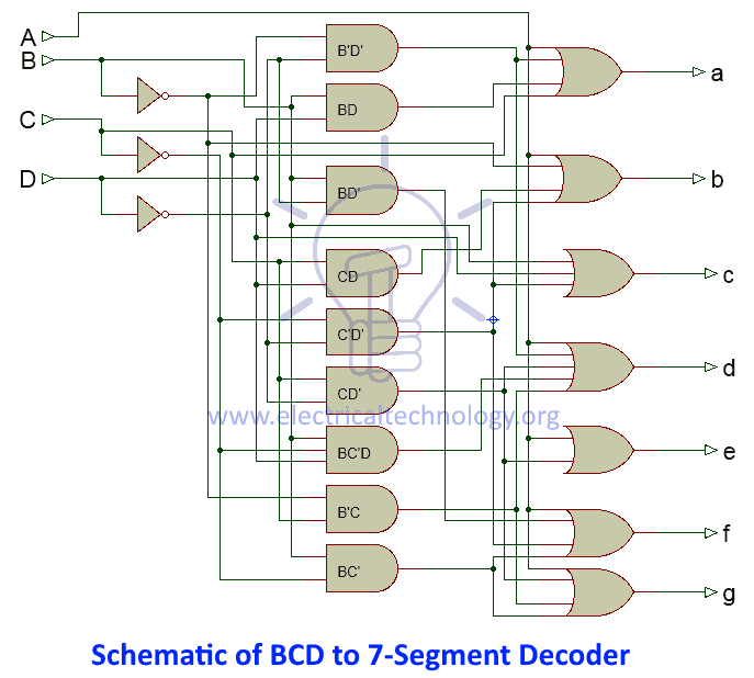
Step 4: The final step involves drawing a combinational logic circuit for each output signal. Once the task was accomplished, a combinational logic circuit can be drawn using 4 inputs (A,B,C,D)and a 7- segment display (a,b,c,d,e,f,g) as output.

Display Decoder Circuit Operation
The circuit operation can be understood through the truth table itself. When all the inputs are connected to low logic , the output of the combinational logic circuit would be so as to drive all the output LEDs except ‘g’ to conduction. Thus the number 0 will be displayed. Similar operation would take place for all other combinations of the input switches.
Note: Also read the interesting post – LED Blinking Circuits
Practically BCD to 7 segment decoders are available in form of integrated circuits such as 74LS47. Apart from regular 4 input pins and 7 output pins, it consists of a lamping test pin used for segment testing, ripple blanking input pin used to blank off zeros in multiple display systems, ripple blanking output pin used for cascading purposes and a blanking input pin.
Back to top
Applications of Display Decoder Circuit
- This circuit can be modified using timers and counters to display the number of clock pulses.
- This circuit can be modified to develop an alphabet display system instead of a decimal number display system.
- It can be used as a timer circuit.
[Also Read: How To Make an Adjustable Timer ]
Limitations of Display Decoder Circuit
- This circuit involves lot of logic gates and is quite complex.
- Timing delay by each logic gate is a matter of concern and this circuit might not produce accurate results when used to display count of pulses.
- This is a theoretical circuit and may require few modifications.
Related Posts:
- 7 Segment Display Pinout
- Seven Segment Displays
- Decade Counter Circuit: Truth Table, D Flip Flop, Diagram
- Arduino 4-Digit 7-Segment LED Display
- Digital Stopwatch Circuit
- Binary Encoders And Their Applications
39 Responses
it is so help full for our project,,,,,
You may want to double check you Boolean algebra on some of the k-maps. Especially for c, because you have; c = B + C’ + D I get from the k-map c = B + C’D
c = B + C’ + D is correct
Your may be wrong
K-map for b is wrong. m(1) mistakenly became a zero in the map.
The truth table is for a common anode display where logic low enables the segment.
You are right…
is ther k-map of the e right?? the 1001 should be a 0
Your sum of minterms for b = F2 (A, B, C, D) = ∑m (0, 1, 2, 3, 4, 7, 8, 9), but this doesn’t translate to the map for b.
This is very easy if we did practice otherwise we can’t do..
Tank`s it`s very good
frankly, it helped me as i were doing an assignment, i have to thank the publisher as well as those who prepare this unique information.
Truth table is for Common Anode display……
Yes it is. And it has errors, ironically even for column ‘a’, in the correctly stated paragraph in the text right above it. There are other errors, as pointed out by others and to which the reply has been, “No, it’s correct.” — when it clearly is not. So really, I’m thinking this entire article is plagiarised from different (errant) locations, by someone who hasn’t a clue. WHY? :-/ sigh
Useful article however there is an error on the diagram on the OR gate for the ‘f’ output the first and last pins should not be connected. There is no node drawn so this is just clearly a mistake in drawing the diagram rather than a logic mistake.
i think ‘a’ is wrong a should be A+C+BD+A’B’D’
yeah i think so
truth table for output ‘d’ is right but when filling the K-Map m(9) has been filled as 1 whereas it should have been 0 according to the simplification…as a result 1 term i.e. ‘A’ is extra in the output ‘d’.
d ( 0,2,3,5,6,8) but in k-map you plot it d( 0,2,3,5,6,8,9) so its wrong i think .
d is wrong ……::;d=(023568) but you plot it d=(0235689)
Can someone explain me about the common cathode and common anode concepts? I want to how they can affect the circuit if we used one after another? Thanks
In common cathode. the outputs are connected and grounded. Inputs to activate the segments are a logical 1. (positive voltage)
In common anode, the anodes are connected and power is applied. Inputs to activate the segments are a logical 0 (ground)
The Truth Table listed above is for a common anode, not a common cathode. To get the Truth Table for a common cathode, flip all the ones and zeros for outputs a-g.
its really helpful i wanna thank the publisher for great work he/she did.
When making K-map simplifications, you can’t form groups of 12 like the one for the function C. You can create groups of 2,4,8,16,32,64 etc. ( all are powers of 2) .
For the display of 9 we consider ‘d’ right? As well as for 6 we consider ‘a’ Den the k_map and all changes
Check please, isn’t the circuit for common anode???
Is there d is right? How can you make BC’D??? I cannot make it…
thanks to the publisher
I am very glad because it is very very easy to understand.
Thank you. It’s really helpful.
What is the logic behind its ( bcd to seven segment decorder ) truth table how it is made?
very good. thanks
thanks sir very easy and simple explanation.
I think you make a mistake in this equation a = F1 (A, B, C, D) = ∑m (0, 2, 3, 5, 7, 8, 9). You missed the 6. It should be a = F1 (A, B, C, D) = ∑m (0, 2, 3, 5, 6, 7, 8, 9)
Above table is for common anode, but the k map is for common cathode
AIM: To design and construct a circuit that is capable of accepting a 4 bit binary input and displaying the decimal output on two seven segment displays using a MUX, ADDER and COMPARATOR. CAN YOU PLEASE HELP
One mistake was nuruddin said, otherwise it is good and very helpful.
It is easy to understand when the 7 segments logic diagrams are drawn separately for each.
Leave a Reply Cancel reply
Your email address will not be published. Required fields are marked *
Get our Latest Newletters
Get great content that you love. No ads or spams, we promise.

How To Guides
Android Apple Windows Email YouTube Instagram SnapChat Gaming Discord Cloud Storage Google Sheets
Product Reviews
Home & Security Camera Motherboard PC & PC Accessories Laptops Speakers Car Accessories Air Conditioner Lawn & Garden Software Modem & Router
For Students
Electronics Projects Arduino Projects Embedded Free Circuits Mini Projects Robotics Sensor Cables & Wires RV Systems Solar
Interesting
Insights Tutorials Upcoming Sales Usernames Symbols Calculators Courses Deals Our Story
- Affiliate Disclosure
- Terms and Conditions
- Privacy Policy
Copyright © 2024 Electronicshub.org
- Engineering Mathematics
- Discrete Mathematics
- Operating System
- Computer Networks
- Digital Logic and Design
- C Programming
- Data Structures
- Theory of Computation
- Compiler Design
- Computer Org and Architecture
BCD to 7 Segment Decoder
Prerequisite –
Number System and base conversions
Binary Coded Decimal (BCD)
BCD is the encoding scheme each of the decimal numbers(0-9) is represented by its equivalent binary pattern(which is generally of 4-bits).
Seven segment
Seven Segment display is an electronic device which consists of seven Light Emitting Diodes (LEDs) arranged in a some definite pattern (common cathode or common anode type), which is used to display Hexadecimal numerals(in this case decimal numbers, as input is BCD i.e., 0-9). Two types of seven segment LED display:
- Common Cathode Type: In this type of display all cathodes of the seven LEDs are connected together to the ground or -Vcc(hence, common cathode) and LED displays digits when some ‘HIGH’ signal is supplied to the individual anodes.
- Common Anode Type: In this type of display all the anodes of the seven LEDs are connected to battery or +Vcc and LED displays digits when some ‘LOW’ signal is supplied to the individual cathodes.
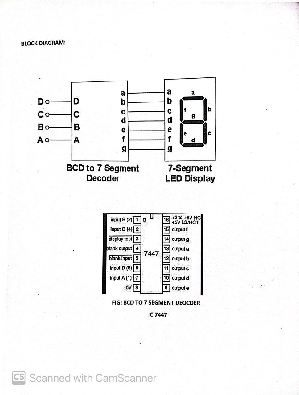
But, seven segment display does not work by directly supplying voltage to different segments of LEDs. First, our decimal number is changed to its BCD equivalent signal then BCD to seven segment decoder converts that signals to the form which is fed to seven segment display. This BCD to seven segment decoder has four input lines (A, B, C and D) and 7 output lines (a, b, c, d, e, f and g), this output is given to seven segment LED display which displays the decimal number depending upon inputs.

Truth Table
For common cathode type BCD to seven segment decoder:

Note –
- For Common Anode type seven segment LED display, we only have to interchange all ‘0s’ and ‘1s’ in the output side i.e., (for a, b, c, d, e, f, and g replace all ‘1’ by ‘0’ and vice versa) and solve using K-map.
- Output for first combination of inputs (A, B, C and D) in Truth Table corresponds to ‘0’ and last combination corresponds to ‘9’. Similarly rest corresponds from 2 to 8 from top to bottom.
- BCD numbers only range from 0 to 9,thus rest inputs from 10-F are invalid inputs.
Example –

Explanation –
For combination where all the inputs (A, B, C and D) are zero (see Truth Table), our output lines are a = 1, b = 1, c = 1, d = 1, e = 1, f = 1 and g = 0. So 7 segment display shows ‘zero’ as output. Similarly, for combination where one of the input is one (D = 1) and rest are zero, our output lines are a = 0, b = 1, c = 1, d = 0, e = 0, f = 0 and g = 0. So only LEDs ‘b’ and ‘c’ (see diagram above) will glow and 7 segment display shows ‘one’ as output.

Applications
- Computerized Clocks: BCD to 7-fragment decoders are utilized in advanced tickers to show time in hours, minutes, and seconds by changing over the paired time information into decipherable digits.
- Counters and Clocks: In counters and clocks, these decoders drive the 7-portion presentations to show the count value or passed time, making them fundamental in different counting and timing gadgets.
- Adding machines: Fundamental mini-computers use BCD to 7-section decoders to change over-paired coded decimal results from the number cruncher’s processor into mathematical digits on the showcase.
- Computerized Meters: They are utilized in computerized voltmeters, ammeters, and recurrence meters to show estimation readings in a mathematical configuration, further developing lucidity.
- Diminished Part Count: Limits the quantity of parts expected to control a 7-portion show.
- Further developed Dependability: Gives a strong and solid change from BCD to show portions.
- Simplicity of Mix: Smoothes out the method involved with incorporating mathematical presentations into advanced frameworks.
Disadvantages
- Cost for Straightforward Applications: Utilizing a dedicated decoder IC may be more costly than less complex answers for essential necessities.
- Speed Limits: Execution is limited by the decoder’s handling speed, which is inadmissible for fast applications.
- Size Imperatives: The actual size of the decoder IC may not fit in minimized plans.
Conclusions
BCD to 7-section decoders improve on the plan of mathematical showcases by changing over BCD inputs into signals for 7-portion shows, decreasing intricacy and part count. They are practical and dependable for direct applications, offering convenience and decreasing plan exertion. Also, their presentation and actual size may not suit all applications. By and large, while BCD to 7-fragment decoders are valuable for some standard presentation applications, cautious consideration of their constraints is essential for an ideal plan.
Frequently Asked Questions on BCD to 7 Segment Decoder-FAQs
What is a bcd to 7-fragment decoder.
A BCD to 7-section decoder is a computerized circuit that changes over parallel coded decimal (BCD) contributions to signals that drive a 7-fragment show, empowering it to show decimal digits.
How does a BCD to 7-fragment decoder work?
The decoder takes a 4-cycle BCD input and makes an interpretation of it into a bunch of results that light up the proper fragments on a 7-portion show to address the corresponding decimal digit.
What kinds of showcases might a BCD to 7-fragment decoder at any point drive?
It explicitly drives 7-section shows, which are ordinarily utilized for showing mathematical digits in gadgets like advanced timekeepers, counters, and estimation instruments.
Could a BCD to 7-section decoder at any point be utilized for multi-digit shows?
Indeed, various decoders can be flowed to drive multi-digit shows, yet this requires cautious timing and control to oversee which digit is shown at a given time.
What are the normal uses of BCD to 7-fragment decoders?
They are ordinarily utilized in computerized timekeepers, counters, recurrence meters, and different gadgets where numeric information should be shown in a comprehensible manner.
Similar Reads
- Digital Logic
Improve your Coding Skills with Practice
What kind of Experience do you want to share?
- Switch skin
Home > Electronics > Combinational Digital Circuits > BCD to 7-Segment Display Decoder – Construction, Circuit & Operation
BCD to 7-Segment Display Decoder – Construction, Circuit & Operation
Bcd to 7-segment display decoder.
Table of Contents
Introduction
A digital or binary decoder is a digital combinational logic circuit which can convert one form of digital code into another form.
BCD to 7-segment display decoder is a special decoder which can convert binary coded decimals into another form which can be easily displayed through a 7-segment display .
BCD stands for binary coded decimal . It is a digital numbering system in which we can represent each decimal number using 4 bits of binary numbers.
There are 10 digits in the decimal system. To represent all 10 digits we need 10 combinations of 4 binary bits.

A digital system like a computer can understand and easily read a large number in binary format. However, a human cannot read large binary numbers. To solve this problem we need to display it as a decimal digit using 7-segment display.
7-Segment Display
It is a digital device that can be used for displaying decimal number, alphabets, and characters.

7-Segment display contains 7 LED segments arranged in a shape given in figure above. Generally, there are 8 input pins in a 7-Segment display. 7 input pins for each of the 7 LEDs and one pin for the common terminal.
Related Posts:
- Binary Encoder – Construction, Types & Applications
- Binary Multiplier – Types & Binary Multiplication Calculator
There are two types of 7-Segment displays.
Common Cathode
In such type of 7-segment display, all the cathodes of the 7 LEDs are connected together to form a common terminal. It should be connected to GND or logic ‘0’ during its operation.
To illuminate any LED of the display, you need to supply logic ‘1’ to its corresponding input pin.
Common Anode
The type of 7-Segment display in which all the anode terminals of 7 LEDs are connected together to form common anode terminal. This terminal should be connected with Vcc or logic ‘1’ during its operation.
To illuminate any of the LED segments we need to provide logic ‘0’ to it.
- Related Post: Seven Segment Display: 7-Segment Display Types, Working & Applications
Working of 7-Segment Display (LED & LCD) Circuit
7 LED segments of the display and their pins are “ a”, “b”, “c”, “d”, “e”, “f” & “g” as shown in the figure given below. Each of the pins will illuminate the specific segment only.
We assume common cathode LED segment as our example.
Suppose we want to display digit ‘0’, in order to display 0, we need to turn on “a”, “b”, “c”, “d”, “e”, “f”. & turn-off the “g”. which would look like the figure given below.

7-Segment Display Segments for all Numbers
Display combination of decimal numbers is given below.
Digit 1 : to display the digit 1 we need to turn on the segments b, c. and turn off the LED segments a, d, e, f, and g. This configuration will result in the display as shown in the figure below.
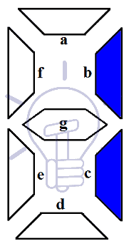
Digit 2 : to display the digit 2 we need to turn on the segments a, b, d, e, g. and turn off the LED segments c, f. This configuration will result in the display as shown in the figure below.
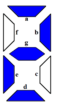
Digit 3 : to display the digit 3 we need to turn on the segments a, b, c, d, g. and turn off the LED segments e, f. This configuration will result in the display as shown in the figure below.
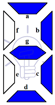
Digit 4 : to display the digit 4 we need to turn on the segments b, c, f, g. and turn off the LED segments a, d, e. This configuration will result in the display as shown in the figure below.
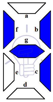
Digit 5 : to display the digit 5 we need to turn on the segments a, c, d, f, g. and turn off the LED segments b, e. This configuration will result in the display as shown in the figure below.
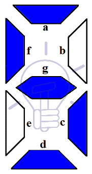
Digit 6 : to display the digit 6 we need to turn on the segments a, c, d, e, f, g. and turn off the LED segments b. This configuration will result in the display as shown in the figure below.

Digit 7 : to display the digit 7 we need to turn on the segments a, b, c. and turn off the LED segments d, e, f, g. This configuration will result in the display as shown in the figure below.
- Related article: DEMUX – Demultiplexer | Types, Construction & Applications
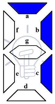
Digit 8 : to display the digit 8 we need to turn on the segments a, b, c, d, e, g only. This configuration will result in the display as shown in the figure below.

Digit 9 : to display the digit 2 we need to turn on the segments a, b, c, d, f, g. and turn off the LED segments e. This configuration will result in the display as shown in the figure below.

To display these digits using binary numbers we need to decode these binary numbers into the combination used for each pattern or display using Decoder.
Related post: Binary Adder & Subtractor – Construction, Types & Applications
Truth Table
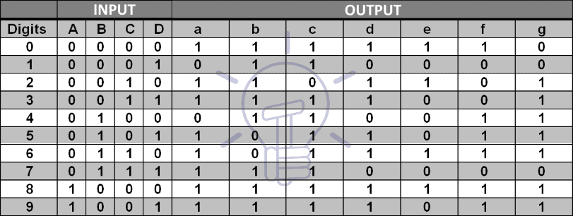
Assume common cathode 7-Segment display. Suppose the binary input ABCD to the decoder and output a, b, c, d, e, f, & g for the display.

Karnaugh Maps Simplification
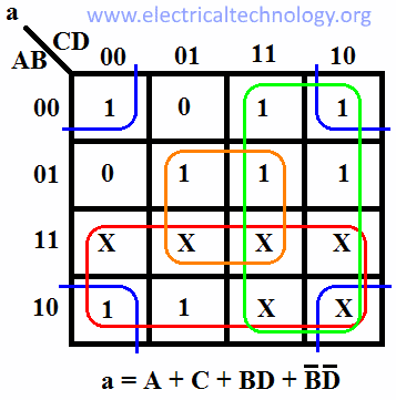
For other combinations of input, the output is “ don’t care X ” as there are no more digits to display. We will derive the expression for each output using Karnaugh map (K-MAP ).
For output a:
For output b:
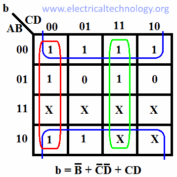
For output c:
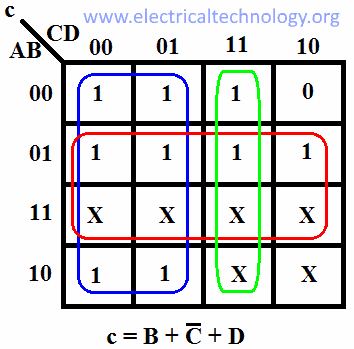
For output d:

For output e:
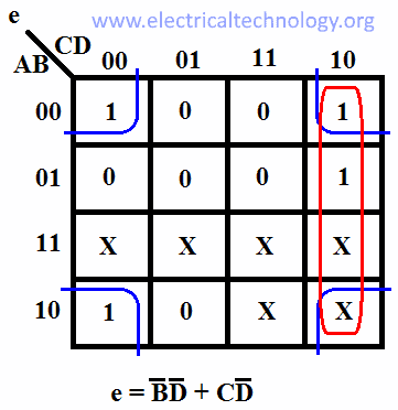
For output f:
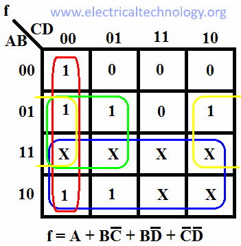
For output g:

- Ring Counter & Johnson Counter – Construction & Operation
- Digital Flip-Flops – SR, D, JK and T Flip Flops
7-Segment Display Decoder Circuit
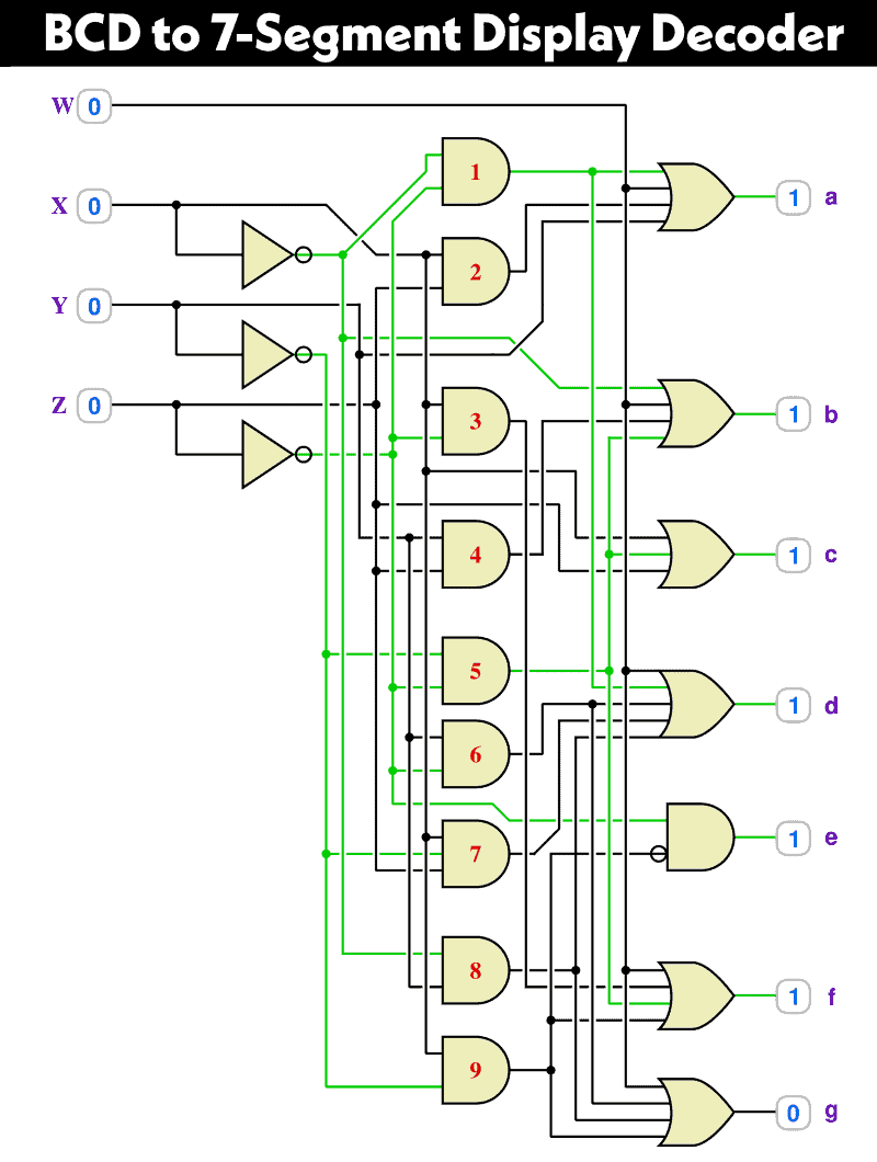
The following is the updated version of the BCD to 7-Segment Display Decoder circuit (replaced the ABCD inputs with WXYZ).
Click image to enlarge
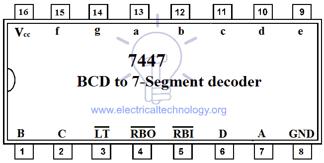
BCD to 7-Segment Decoder IC & Pin outs
7447 BCD to 7-Segment Decoder
The commonly used IC for BCD to 7-segment decoding is 7447 . The pin configuration of 7447 is given in the figure below.
- Comparator and Digital Magnitude Comparator
- Sum Of Product (SOP) & Product Of Sum (POS)
Application of BCD to Display Decoder
- This circuit can be used as a timer circuit.
- With little modification, it can be also used to display the number clock pulses.
- It can also be used with modification to display alphabet display system instead of decimal display system.
- 7-Segment display are mostly used in digital clocks, electronic meters, odometers as well as LCD application due to low current consumption.
- They are also used in various measuring instruments, digital watches and digital counters
You May Also Read:
- Digital Logic AND Gate
- Digital Logic OR Gate
- Logic NOT Gate
- Digital Logic NOR Gate
- Exclusive-NOR (XNOR) Gate
- Digital Logic NAND Gate
Electrical Technology
Related articles.
Emergency LED Light Circuit – DP-716 Rechargeable 30 LED’s Lights Schematic

Clap Switch Circuit Using IC 555 Timer & Without Timer
Traffic Light Control Electronic Project using IC 4017 & 555 Timer

How to Make Christmas LED & Bulb Blinking Light String Circuit at Home

Main Difference Between Electrical and Electronic Engineering?
The Main Difference between Active and Passive Components
The diagram for the 7-Segment Display Decoder Circuit is incorrect. The 2 input Or gate that is being fed into segment e is incorrectly shown to be input by a+cd’, while it should be b’d’+cd’
The “Schematic of BCD to 7 Segment Decoder” is not correct. We see that logic OR for segement g and the logic OR for segment e are directly interconnected. Every time a segment g is on a segment e will be on. Thus “0” will not be displayable.
also a 9 is not possible
The e and g is incorrect! E is ¬(BD) + C¬D. There is an A connected… Why?
The g output is A + B¬C + B¬D + ¬BC. There is no C¬D
Leave a Reply Cancel reply
Your email address will not be published. Required fields are marked *

Analysis of Functions of BCD-TO-7-segment Decoder / Driver and Operation of 7-segment LED Display
Aim of the experiment.
The principal objective of this experiment is to fully understand the functions of a BCD-to-7-segment decoder (IC 7447) and use it to control the operations of a common-anode 7-segment LED display.
To implement BCD to 7 Segment LED display decoder
The purpose of this experiment is to design and implement combinatorial logic that will decode a 4-bit BCD input to a seven segment LED display.
Binary Coded Decimal (BCD or “8421” BCD) numbers are made up using just 4 data bits (a nibble or half a byte) similar to the Hexadecimal numbers we saw in the binary tutorial, but unlike hexadecimal numbers that range in full from 0 through to F, BCD numbers only range from 0 to 9, with the binary number patterns of 1010 through to 1111 (A to F) being invalid inputs for this type of display and so are not used.
BCD to 7-Segment Display Decoders
A binary coded decimal (BCD) to 7-segment display decoder such as the TTL 74LS47 or 74LS48, have 4 BCD inputs and 7 output lines, one for each LED segment. This allows a smaller 4-bit binary number (half a byte) to be used to display all the denary numbers from 0 to 9 and by adding two displays together, a full range of numbers from 00 to 99 can be displayed with just a single byte of 8 data bits.
- AC Circuits
- Attenuators
- Binary Numbers
- Boolean Algebra
- Combinational Logic
- DC Circuits
- Electromagnetism
- Input/Output Devices
- Logic Gates
- Miscellaneous Circuits
- Operational Amplifiers
- Power Electronics
- Power Supplies
- RC Networks
- Sequential Logic
- Transformers
- Transistors
- Waveform Generators
- Premium content
- Further Education
- Sitemap Page
- Connectivity
- Input and Output Devices
- Premium Content
Advertisement
Display Decoder
A Display Decoder is a combinational circuit which decodes and n-bit input value into a number of output lines to drive a display
A Digital Decoder IC, is a device which converts one digital format into another and one of the most commonly used devices for doing this is called the Binary Coded Decimal (BCD) to 7-Segment Display Decoder.
7-segment LED (Light Emitting Diode) or LCD (Liquid Crystal Display) type displays, provide a very convenient way of displaying information or digital data in the form of numbers, letters or even alpha-numerical characters.
Typically 7-segment displays consist of seven individual coloured LED’s (called the segments), within one single display package. In order to produce the required numbers or HEX characters from 0 to 9 and A to F respectively, on the display the correct combination of LED segments need to be illuminated and BCD to 7-segment Display Decoders such as the 74LS47 do just that.
A standard 7-segment LED display generally has eight (8) input connections, one for each LED segment and one that acts as a common terminal or connection for all the internal display segments. Some single displays have also have an additional input pin to display a decimal point in their lower right or left hand corner.
In electronics there are two important types of 7-segment LED digital display.
- 1. The Common Cathode Display (CCD) – In the common cathode display, all the cathode connections of the LED’s are joined together to logic “0” or ground. The individual segments are illuminated by application of a “HIGH”, logic “1” signal to the individual Anode terminals.
- 2. The Common Anode Display (CAD) – In the common anode display, all the anode connections of the LED’s are joined together to logic “1” and the individual segments are illuminated by connecting the individual Cathode terminals to a “LOW”, logic “0” signal.
Common Cathode and Common Anode Format
Electrical connection of the individual diodes for a common cathode display and a common anode display and by illuminating each light emitting diode individually, they can be made to display a variety of numbers or characters.
7-Segment Display Decoder Format
So in order to display the number “3” for example, segments a , b , c , d and g would need to be illuminated. If we wanted to display a different number or letter then a different set of segments would need to be illuminated. Then for a 7-segment display, we can produce a truth table giving the segments that need to be illuminated in order to produce the required character as shown below.
Truth Table for a 7-segment display
7-Segment Display Elements for all Numbers.
It can be seen that to display any single digit number from 0 to 9 in binary or letters from A to F in hexadecimal, we would require seven separate segment connections plus one additional connection for the LED’s “common” connection. Also as the segments are basically a standard light emitting diode, the driving circuit would need to produce up to 20mA of current to illuminate each individual segment and to display the number “8”, all seven segments would need to be lit resulting a total current of nearly 140mA, (8 x 20mA).
Obviously, the use of so many connections and power consumption is impractical for some electronic or microprocessor based circuits and so in order to reduce the number of signal lines required to drive just one single display, display decoders such as the BCD to 7-Segment Display Decoder and Driver IC’s are used instead.
Binary Coded Decimal
Binary Coded Decimal (BCD or “8421” BCD) numbers are made up using just 4 data bits (a nibble or half a byte) similar to the Hexadecimal numbers we saw in the binary tutorial, but unlike hexadecimal numbers that range in full from 0 through to F , BCD numbers only range from 0 to 9 , with the binary number patterns of 1010 through to 1111 (A to F) being invalid inputs for this type of display and so are not used as shown below.
BCD to 7-Segment Display Decoders
A binary coded decimal (BCD) to 7-segment display decoder such as the TTL 74LS47 or 74LS48, have 4 BCD inputs and 7 output lines, one for each LED segment. This allows a smaller 4-bit binary number (half a byte) to be used to display all the denary numbers from 0 to 9 and by adding two displays together, a full range of numbers from 00 to 99 can be displayed with just a single byte of eight data bits.
BCD to 7-Segment Display Decoder
The use of packed BCD allows two BCD digits to be stored within a single byte (8-bits) of data, allowing a single data byte to hold a BCD number in the range of 00 to 99 .
An example of the 4-bit BCD input ( 0100 ) representing the number “4” is given below.
Display Decoder Example No1
In practice current limiting resistors of about 150Ω to 220Ω would be connected in series between the decoder/driver chip and each LED display segment to limit the maximum current flow. There are different display decoders and drivers available for the different types of available displays, either LED or LCD. For example, the 74LS48 for common-cathode LED types, the 74LS47 for common-anode LED types, or the CMOS CD4543 for liquid crystal display (LCD) types.
Liquid crystal displays (LCD´s) have one major advantage over similar LED types in that they consume much less power and nowadays, both LCD and LED displays are combined together to form larger Dot-Matrix Alphanumeric type displays which can show letters and characters as well as numbers in standard Red or Tri-colour outputs.

Read more Tutorials inCombinational Logic
- 1. Combinational Logic Circuits
- 2. The Multiplexer
- 3. The Demultiplexer
- 4. Priority Encoder
- 5. Binary Decoder
- 6. Display Decoder
- 7. Binary Adder
- 8. Digital Comparator
- 9. Binary Subtractor
- 10. Bus Transceiver
- 11. Transmission Gate
- 12. Analogue to Digital Converter
- 13. Binary Weighted DAC
- 14. R-2R DAC
131 Comments
Notify me of follow-up comments by email.
i want to know about the bcd code to 7 segment decoder and how i can apply in the multisim.
It’s very good Please explain how you can coding and examples of projects Thank you for your faithly
Dear Sir Please provide quotation :-
COUNTER 7-digits LCDCH-7A 7-DIGITS LCDCONCH
23940 27301 48030 48012 17602 16742 17504
Heelo guys. Chai pilo.
aap pio garma garm
Excellent tutorials
lucky to joint this information to learn basically.
Thanks and regards
Good Morning sir. Very good information in precise form for learners faculty and applicators. Thanks.
Im happy to join this converstion
Having just numbers, for the bottom right (c segment) 1buffer 2notgate 3buffer 4buffer (will only not light up if 2 (only number without ‘c’ segment))
How to take carry out signal one decoder to other decoder for cascading more ics and get more digit display
Utilize a latching serial interface on the bcd input. You can then use far less pins to drive many digits.
It is required to display English Characters i.e. A-Z using 7-Segment Display.The circuit should have 5 inputs ,since the English characters are 26 only.The letter A has the code 1 =“00001”, and the Z has the code “11010”. Try to represent the characters as small letter, if conflict occurs , use the shape of the Capital letter. Analyze the specifications to build the require design and what characters you think couldn’t be represented?. Follow the 5-step design procedure also calculate the gate-input-cost for implementation of the design.
Z, K, M, N. Q, T
Many – I stopped counting them.
Hello everyone
Why do we use nand gate on bcd to 7 segment display decoder?
8-3 7 segment encoder
- Privacy Policy
- Terms of Use
- Contact Sales
- Media Guide Request
- Electronic Products
- Power Electronics News
- Planet Analog
- ElectroSchematics
- Datasheets.com
- Electronics Know How
- The Channelist
- EE Times Asia
- EE Times China
- EE Times India
- EE Times Japan
- EE Times Taiwan

Digital Electronics Laboratory
Virtual lab, iit guwahati, to study a bcd to 7 segment led display.
- Sample Output
The purpose of this experiment is to design and implement combinatorial logic that will decode a 4-bit BCD input to a seven segment LED display.
BCD to 7-Segment Display Decoders
Bcd to 7-segment decoder.

The use of packed BCD allows two BCD digits to be stored within a single byte (8-bits) of data, allowing a single data byte to hold a BCD number in the range of 0 to 9

In practice current limiting resistors of about 150Ω to 220Ω would be connected in series between the decoder/driver chip and each LED display segment to limit the maximum current flow. There are different display decoders and drivers available for the different types of available displays, either LED or LCD. For example, the 74LS48 for common-cathode LED types, the 74LS47 for common-anode LED types, or the CMOS CD4543 for liquid crystal display (LCD) types. Liquid crystal displays (LCD’s) have one major advantage over similar LED types in that they consume much less power and nowadays, both LCD and LED displays are combined together to form larger Dot-Matrix Alphanumeric type displays which can show letters and characters as well as numbers in standard Red or Tri-colour outputs.
Components used:
We used the following components for this experiment-
- IC 7447 Datasheet -->
- 7 segment Display Datasheet -->
How to make connection:
After Starting the experiment first click on the Components button to get component list. Now you can Drag and Drop any component in the circuit designing area. To make connection between components, just click on the Blue bubble of any components and Drag it to another Blue bubble of the same or any other components. To delete connection or to remove any component use Double click on that component or connection.
How to run:
After connenting all the required components,click on the Start button and you will get a new start window, where you can give the inputs. After this,you click the run button and finally the outputs are shown.
Two binary digits Three binary digits Four binary digits None of the Mentioned
1) Continuous b) Discrete c) binary d) None of the Mentioned
a) Decoding b) Encoding c) Coding d) None of the Mentioned
a) 1010 b) 01010 c) 00010000 d) 001010
a) Gray Code b) Excess-3 c) BCD d) Hexadecimal
Decoder with 7 segment display
BCD to 7-segment Decoder
- A BCD to 7-segment Decoder generates 7 outputs from a BCD (4-bit) input for driving a 7-segment LED display device to display BCD digits.
- A 7-segment display consists of seven segments designated as a, b, c, d, e, f and g in a clockwise sequence. An optional DP decimal point (an "eighth segment") is used for the display of non-integer numbers.
- In a 7-segment LED display, either all the anodes or all the cathodes of the LEDs in the seven segments are tied together and brought out at a single pin, and the device is accordingly called either a common-anode or a common-cathode display. In this experiment, we will be using a common-cathode display.
- The objective of this experiment is to design, assemble and test a BCD to 7-segment Decoder generating these seven outputs. Note that each segment is lighted when the corresponding decoder output, also denoted by a, b, c, d, e, f and g, is HIGH.

BCD to 7-segment Decoder | A | B | C | D | a | b | c | d | e | f | g | Digit | |---|---|---|---|---|---|---|---|---|---|---|---| | 0 | 0 | 0 | 0 |1 |1 |1 |1 |1 |1 | 0 | 0 | | 0 | 0 | 0 | 1 |0 |1 |1 |0 |0 |0 | 0 | 1 | | 0 | 0 | 1 | 0 |1 |1 |0 |1 |1 |0 | 1 | 2 | | 0 | 0 | 1 | 1 |1 |1 |1 |1 |0 |0 | 1 | 3 | | 0 | 1 | 0 | 0 |0 |1 |1 |0 |0 |1 | 1 | 4 | | 0 | 1 | 0 | 1 |1 |0 |1 |1 |0 |1 | 1 | 5 | | 0 | 1 | 1 | 0 |1 |0 |1 |1 |1 |1 | 1 | 6 | | 0 | 1 | 1 | 1 |1 |1 |1 |0 |0 |0 | 0 | 7 | | 1 | 0 | 0 | 0 |1 |1 |1 |1 |1 |1 | 1 | 8 | | 1 | 0 | 0 | 1 |1 |1 |1 |1 |0 |1 | 1 | 9 |
7 segment display |Digit | Off Segments| |------|-------------| |0 | g | |1 | a,d,e,f,g | |2 |c,f | |3 |e,f | |4 |a,d,e | |5 | b,e | |6 | b | |7 |d,e,f,g | |8 | - | |9 |e |
BCD to 7 Segment Decoder

Introduction: BCD to 7 Segment Decoder

We have made a BCD to 7 segment decoder, it was my lab project and we thought that we should upload it so why not!
A Binary-Coded Decimal (BCD) to Seven-Segment Decoder is a digital circuit commonly implemented using ICs like the 7447. It takes a 4-bit BCD input, representing decimal digits, and converts it into signals to illuminate the appropriate segments on a seven-segment display. Each BCD input corresponds to a specific decimal digit, and the decoder's output activates the necessary segments to visually display the digit. This type of decoder finds widespread use in digital display applications such as clocks and calculators, where numerical information needs to be presented on seven-segment displays. Its functionality simplifies the process of converting binary-coded decimal data into a format suitable for showcasing numerical information in various electronic devices.
BCD decoder is a complex circuit, to make it easy I have used IC 7447. This IC has 16 pins, pin 8 for ground and 16 for VCC. Pin 3 for display test, whether to check if all segments of display are working or not. Pins 4 and 5 are blank I/O. Pin 1 2 6 and 7 are four inputs and pin 9 to 15 belongs to each segment of LED display.
For display I have used a common anode LED. It means to turn on the device it must be put in VCC.
I used a resistor of 1 kilo ohm, just to be on safer side and protect the display.
In circuit diagram the GATES used are as follow:
GATES
NUMBERS OF GATES
AND 9
OR 8
NOT 4
Step 1: Working

WORKING:
Segment 'a':
Segment 'a' represents the top horizontal segment of the seven-segment display. It is activated to form the top part of numerical digits.
Segment 'b':
Segment 'b' represents the top-right diagonal segment. It is activated to form diagonal elements in characters.
Segment 'c':
Segment 'c' represents the bottom-right diagonal segment.
Segment 'd':
Segment 'd' represents the bottom horizontal segment. It is activated to form the bottom part of numerical digits.
Segment 'e':
Segment 'e' represents the bottom-left diagonal segment. It is activated to form diagonal elements in characters.
Segment 'f':
Segment 'f' represents the top-left diagonal segment. It is activated to form diagonal elements in characters.
Segment 'g':
Segment 'g' represents the middle horizontal segment. It is activated to form the middle part of numerical digits.
BCD Input Mapping:
Each BCD input (a 4-bit binary number) corresponds to a specific decimal digit. The decoder maps each BCD input to the activation or deactivation of the segments to display the corresponding digit.
Example:
For example, let's consider the BCD input 0100, which corresponds to the decimal digit 4.The mapping for segment activation would be:
a and b are deactivated.
c is activated.
d is deactivated.
e, f, and g are activated.
When these activations are applied to the seven-segment display, it forms the numeral '4' on the display.
Step 2: Circuit Diagram

internal working of circuit.
Step 3: Block Diagram
Step 4: K MAP


IMAGES
VIDEO
COMMENTS
A common cathode 7 segment display consists of 8 pins - 7 input pins labeled from 'a' to 'g' and 8 th pin as common ground pin. 7 Segment Display Decoder Circuit Design. Step 1: The first step of the design involves analysis of the common cathode 7-segment display. A 7-segment display consists of an arrangement of LEDs in an 'H' form.
#for f: #for g: Applications. Computerized Clocks: BCD to 7-fragment decoders are utilized in advanced tickers to show time in hours, minutes, and seconds by changing over the paired time information into decipherable digits. Counters and Clocks: In counters and clocks, these decoders drive the 7-portion presentations to show the count value or passed time, making them fundamental in different ...
Commercially available TTL 7447 BCD-to-seven segment decoder/driver, logic symbol of which is shown in Figure 3 (a), can be conveniently used for controlling a common-anode type LED display device. The BCD number to be decoded is applied to the inputs D, C, B, and A. When the lamp test input (LT) is driven low, all the segments (a to g) are ...
7-Segment Display Segments for all Numbers. Display combination of decimal numbers is given below. Digit 1: to display the digit 1 we need to turn on the segments b, c. and turn off the LED segments a, d, e, f, and g. This configuration will result in the display as shown in the figure below.
Experiment with making this input high (1) and low(0), observing the results on the 7-segment display as you alter the BCD code with the four input switches. After you've learned what the input's function is, connect it to the power supply rail enabling normal operation, and proceed to experiment with the next input (either Lamp Test or ...
Introduction. About the Experiment. How to display decimal numbers 0-9 on a 7-segment LED display. How to display a blank (making all the segments off) How to test the inputs LT (lamp test), ripple blanking input (RBI) and blanking input / ripple blanking output (BI/RBO) of TTL 7447 BCD-to-7-segment decoder. How to blank out the leading 0s in a ...
The principal objective of this experiment is to fully understand the functions of a BCD-to-7-segment decoder (IC 7447) and use it to control the operations of a common-anode 7-segment LED display. Community Links Sakshat Portal Outreach Portal FAQ: Virtual Labs. Contact Us Phone: General Information: 011-26582050 Email: [email protected].
Obtain the TTL 74LS47 BCD to 7-segment decoder from your components kit. Insert the 74LS47 decoder next to the DIP resistors. Provide power to the 74LS47 by connecting pin 16 to +5V and pin 8 to ground. To simulate the BCD input, insert jumper wires from the switches to the 74LS47 as shown in Table 8.3.
BCD (Binary Coded Decimal) is defined as an encoding scheme that represents each decimal number with a 4-bit binary pattern.A Seven segment displays is made up of seven segments, usually Light Emitting Diodes (LEDs) or Liquid Crystal Displays (LCDs), arranged in a specific pattern.. For the display to work, these segments must be driven by specific logic levels.
Here is the block diagram of the Seven Segment LED arrangement. LED‟s are basically of two types- Common Cathode (CC) -All the 8 anode legs uses only one cathode, which is common. Common Anode (CA)-The common leg for all the cathode is of Anode type. n to a maximum of 2 unique output lines. The IC7447 is a BCD to 7-segment pattern converter.
The purpose of this experiment is to design and implement combinatorial logic that will decode a 4-bit BCD input to a seven segment LED display. ... (BCD) to 7-segment display decoder such as the TTL 74LS47 or 74LS48, have 4 BCD inputs and 7 output lines, one for each LED segment. This allows a smaller 4-bit binary number (half a byte) to be ...
A Digital Decoder IC, is a device which converts one digital format into another and one of the most commonly used devices for doing this is called the Binary Coded Decimal (BCD) to 7-Segment Display Decoder.. 7-segment LED (Light Emitting Diode) or LCD (Liquid Crystal Display) type displays, provide a very convenient way of displaying information or digital data in the form of numbers ...
During this experiment students should acquire the basic skills needed to take a simple design description to a working and testable version. M ... the 7447 (BCD to seven-segment decoder driver) will be used. This circuit has a BCD input (DCBA) and seven outputs (abcdefg). The outputs of the 7447 are active low and must be used with a common ...
The purpose of this experiment is to design and implement combinatorial logic that will decode a 4-bit BCD input to a seven segment LED display. ... BCD to 7-Segment Decoder. The use of packed BCD allows two BCD digits to be stored within a single byte (8-bits) of data, allowing a single data byte to hold a BCD number in the range of 0 to 9 ...
In a 7-segment LED display, either all the anodes or all the cathodes of the LEDs in the seven segments are tied together and brought out at a single pin, and the device is accordingly called either a common-anode or a common-cathode display. In this experiment, we will be using a common-cathode display. The objective of this experiment is to ...
Step 4: K MAP. K MAPING. BCD to 7 Segment Decoder: We have made a BCD to 7 segment decoder, it was my lab project and we thought that we should upload it so why not! A Binary-Coded Decimal (BCD) to Seven-Segment Decoder is a digital circuit commonly implemented using ICs like the 7447. It takes a 4….
ion of 7-segment LED Display.Aim of the Experiment :-The Principal objective of this experiment is fully understand of BCD-To-7-segment Decoder ( IC 7447) and use it is to the control t. on of the common-anode 7-segment LED Display.Theory:-The result of a processing unit needs to be convenie. tly displayed to a user for its proper ...
BCD to 7-Segment Decoder. January 2021; Electronics Science Technology and Application 7(4):134; ... Benchmark problems with inputs from 9 to 12 are used in the computational experiments, and the ...
A decoder is a combinational circuit that connects the binary information from 'n' input lines to a maximum of 2n unique output lines. The IC7447 is a BCD to 7-segment pattern converter. The IC7447 takes the Binary Coded Decimal (BCD) as the input and outputs the relevant 7 segment code.